This project was undertaken as part of a class I have just finished, Introduction to Engineering Design. The goal of the class is to begin working in group environments, and simulating a client/designer dynamic in preperation for future projects within the college, as well as reality of course.
Our client was Dr. Gerald Fine, the Director of EPIC, and his initial project description reads as follows:
Vertical Farming: The goal of this project is to build a prototype hydroponic device optimized for the indoor cultivation of edible greens. Considerations 1 include optimizing the frequency and intensity of light to maximize growth, and monitoring and control of CO2, temperature and water levels. A successful prototype will monitor and control at least two of the variables. Ideally, the final device should be capable of being powered solely by solar energy, although the prototype may use wall power. A prototype grow region of 0.5m x 0.5m is required.After meeting in person with Dr. Fine, we were able to clarify several questions we had as well as open a dialog that ended up revealing many details desired in the prototype. Funny enough, we were warned about this meeting by our professor and how it had the potential to comletely rewrite the initial project description. In the end it wasn't as bad as it could've been. In the meeting, we discussed the types of experiments the client wanted to conduct so that we could best accomodate them. The primary focus of the experiments are to check the effects of color temperature and intensity on plants. Additionally, measurement of nutrient levels in the reservoir would be desirable, stackability and modularity and were important, and the line about being powered by solar energy is an incredibly low priority. Arguably the most important outcome of this meeting was that the prototype shall cost no more than $400.
With all of that in mind, my group and I started brainstorming and designing. Given the scope of the course, a lot of these steps were carefully chosen for us, but left the actual designing up to us. We first identified the design space, then wrote a problem statement. We also turned our initial project description and notes from the client meeting into a list of objectives and constraints.
On to actual design work. We looked at the design space and considered several types of hydroponic systems. Among the most common types of hydroponic systems are wick, ebb and flow, and deep water culture. The main diffrenece between all of these system are how a water nutrient solution reaches the roots of the plants.
 |
| Ebb and Flow Diagram |
 |
| Wick System Diagram |
 |
| Deep Water Culture Diagram |
Due to prior experience, simplicity, and capability our group chose to design around the deep water culture type system.
In the grand scheme of things, this project definitely concentrates more on skills relevant electrical and computer engineering than mechanical engineering, which is good because I've been wanting to dig deeper into ECE fields.
A large reservoir, intrinsic to the deep water culture type hydroponic systems, is the heart of our design. Rather than manufacturing this reservoir, we decided it would be best to modify a readily available container. We chose this 27 gallon tote from Amazon due to it's size meeting our grow area constraints, as well as the plastic it's made of being easy to modify.
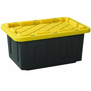 |
| 27 Gallon Tote |
 |
| Original drawings |
As for the rest of the enclosure, we decided to use extruded aluminum framing with appropriate mounting brackets. This decision was encouraged by our professors because they had a lot of it on hand. We liked the the idea of extruded aluminum because it was easy to work with, quite strong for our use, and would resist corrosion. At the end of the design phase, I had finished a rendering of what the skeleton of our system would look like.
 |
| Frame Rendering |
The frame gives support for two bins vertically. These supports also give our lights a point to mount on. In addition to being able to stack two bins vertically, adjusting the design to accomodate more would be quite simple. Ideally, the entire frame would be closed off by some kind of drape to seclude it from the environment outside of the frame. It's a fairly simple design and was a very small portion of the design phase. Most of the work ended up being speccing out sensors and electronics.
Our goal going into this was to measure and record temperature, humidity, CO2, water levels, and electrical conductivity levels of the system. Sensors to measure these variables are readily available from sources such as Adafruit, Digi-key, and Amazon. To measure temperature and humidity, we chose a DHT22 sensor since our professor already had a bunch, and was able to measure within our desired range, with reasonable accuracy. A sensor to measure CO2 was slightly more difficult to find, but with some digging, one turned up on Digi-key. The MG-811 sensor we found seems to be similar to all other MQ sensors except that it's much more expensive, go figure. At nearly $60, this was one of the biggest financial hits of the project, but necessary to meet requirements. The water levels required some thinking. With several ways of measuring water levels, we chose staggered reed switches and a magnetic float over various types of mechanical and electrical solutions. We staggered 4 reed switches at 5 cm intervals and placed them in a PVC tube running the height of the reservoir. A concentric float will sit in the water and trigger the reed switches as the water level changes. Electrical conductivity was the last sensor we wanted to implement. We sought out a more DIY solution as EC sensors, and pH sensors that could be used to measure nutrient levels in the solution were expensive. Inspiration for our sensor was from a blog post by Michael Ratcliffe.
With all of these inputs, we also wanted to have some sort of control over these growth variables. While not ideal, the client had informed us that for our prototype, being able to vent the closed system to an atmosphere suitable for growth would demonstrate the ability of the system to measure growth variables and act accordingly. The three inputs to the system we ended up having were a solenoid valve, a set of fans, and RGBW LED strips. The solenoid valve would connect to a water supply and regulate water levels by opening or closing in response to reed sensor measurements. The fans would demonstrate our ability to vent to a desirable atmosphere, and the RGBW LED strips would provide the variable light source to our system.
After a preliminary design report, and several days waiting, we recieved most of our parts and were able to get building.
The chop saw made pretty clean cuts, but I had to file the ends to make sure I could still slide the fitting in the rails later.
 |
| Etruded aluminum being cut to size with a chop saw. |
The chop saw made pretty clean cuts, but I had to file the ends to make sure I could still slide the fitting in the rails later.
 |
| 2" holes for hydroponic growing baskets |
 |
| All 9 holes cut in the top |
I just cut the holes with a 2" hole cutter, and once again took a file to the edges to try and clean them up a little bit.
 |
| Two members bracketed together |
 |
| Two fans mounted on one of the crossbars. Cable management 0/7 |
I'm cringing inside as I'm about to type "hot glue", but the fans were mounted to the crossbars with hot glue... No excuse here seeing as how, there are mounting holes on the fan, and actually utilizing those would've taken about 30 seconds to figure out... Definitely something that should change, even in a prototype.
Next was all of the electronics. Being the lead mechanical engineer on the team, I was surprised to end up taking on the responsibility of electronics. In the end I'm really glad it happened, because broadening your horizons blah blah blah. Seriously though, a worthwhile experience. Unfortunately however, the struggle trying to figure it all out, coupled with a deadline less than 24 hours away meant that I didn't end up documenting it very well.
From memory though, the DHT22 sensor used a digital output that reported both temperature and humidity. Rather than going into hear, Adafruit has a pretty solid tutorial that I followed. Nothing particularily revolutionary here.
The MG811 sensor was simply analog input to the Raspberry Pi. Problem being that the Raspberry Pi doesn't have any analog input channels. We grabbed a cheap ADC from Adafruit to fix that issue. Again, nothing revolutionary, and I ended up doing some reading on Sparkfun on how SPI communication worked. With little effort, I was reading CO2 levels.
On the output side of the system, we used a relay board to handle the fans and our solenoid for water levels. The board was pretty simple to use. 12 volts into the relay channel, output to the device, and 5 volt logic from the Raspberry Pi to signal each of the relays.
Our LED strips were a little interesting though. It was frustrating because I'm almost 99% sure we had ordered addressable strips, but instead we got regular strips. No big deal, just a bunch more reading to do. After some reading and talk with my teammates we ended up needing to scavenge MOSFETs. With less than a day before the prototype was due, it was definitely stressful, but that's something you deal with sometimes as a procrastinator. Adafruit to save the day again. We didn't follow the tutorial exactly, but reading through it, we got enough info to be able to build the circuit needed to run the LED strips.
Next was all of the software. I've been programming in Python for another class all semester, and RPi has a pretty solid library in Python so it definitely seemed like a winner.
The code to read the DHT22 temperature and humidity sensor, and the MCP3008 ADC was from Adafruit. The rest of the code was simply interpreting input measurements and setting outputs accordingly. After a quick couple of hours I had everything in a functional state, not pretty by any means, but I had a week before demos to clean things up.
After the prototype was all built though, and I had a functioning codebase, I started cleaning things up. I implemented a simple set of logs for all of the growth variables. It was just a set of comma seperated values. Each line of the file contains one measurement, and the timestamp from when it was taken. I simply used the Python time library and time.localtime() function. The date and time can be cleaned up for output if desired, but it's simple and works for my purposes. Each measured variable ended up getting a log file. This makes it easy for the client to get the data they want.
Next was the input for the LED strips. This was a little bit more of a process. Knowing that the client wanted to input color temperature for their experiments, I'd have to do some reading on that conversion from a color temperature to RGB values that the LED strips need. After some research, I found a nice blog post by Tanner Helland, I got it figured out. I rewrote the algorithm from his blog post in Python and was up in running. This is a video taken of the lights cycling through various color temperatures. Please God forgive me, for I have sinned. I have shot video vertically...
Running out of time, our electronics ended up just getting mounted to a piece of HDPE I had lying around from the the L-bracket I made last semester. In a perfect world, we would've had a closed and sealed enclosure or project box. Water tight considering the nature of the project.
I didn't end up writing the end user interface, that was for one of my group members, but I'm really excited with how it turned out. I'm not sure the inner workings, but I do know she used Flask which is a Python web hosting framework. It worked really well for our application. We were able to automatically read sensor data from the log files already written, automatically refresh the page with the new data, as well as take input for the color temperature, and desired intensity of the white lights on the LED strips.
Come demo day, we had a functioning prototype, and were able to demonstrate a working system. Of course, with our fantastic time management there are things we'd do better. We'd remove most if not all of the hot glue. We'd actually implement the EC sensor (ran out of time). We'd make a better housing for all of the electronics. And last but not least, we'd hope to manage our time better. Ordering parts earlier in the semester was partially out of our control, but that would've been desireable.
In the end, I'm proud of what we ended up accomplishing in the sense that I'd assume parents are proud of their children. Obviously it's not a work of art, or an engineering marvel, but it's a step in the learning process.
Specifications:
- Growth area of .36 m x .78 m (.28 m2).
- Measure water level between 0 and 20 cm ± 5 cm.
- Measure CO2 levels between 350 and 10000 ppm.
- Measure relative humidity between 0 and 100% ± 5%.
- Measure temperature between -40 and 125° C ± .2° C.
- Control water level 0 and 20 cm ± 5 cm.
- Control CO2 levels by venting with 4 fans.
- Control temperature by venting with 4 fans.
- Control relative humidity by venting with 4 fans.
- Control color temperature between 600 and 15000 K.
- All variables are reported to the user via a web interface accessible from any computer.
- Color temperature can be controlled via the same web interface variables are reported to.
- All measurements are recorded in a log file that can be saved and analyzed by the user at any time.
Thanks to June Hua, Andrew Muckle, and Armela Murrizi for the help, Professor Carruthers for the guidance, and Dr. Fine for an interesting project!


